Regular Rain Cap
Short Termination
Finishing Cap
Finishing Cone
Adjustable Roof Flashing 30° to 45°
Adjustable Roof Flashing 5° to 30°
Flat Roof Flashing
Storm Collar
Roof Brace (BT)
Guy Wire Band (BH)
Suspension Band
Wall Band Extension
Wall Band
Firestop Radiation Shield
Wall Radiation Shield
Radiation Shield
Adapter CT/CI
Adapter CI/CT
Step Increaser
Reducer/Increaser
Flue Extension
Floor Support
Roof Support (ST/STHT)
Wall Support
Anchor Plate
45° Insulated Elbow
30° Insulated Elbow
15° Insulated Elbow
Locking Band
Insulated Drain Tee Cap
Insulated Tee Cap
135° Tee
90° Tee
Adjustable Insulated Lengths
Straight Lengths
-
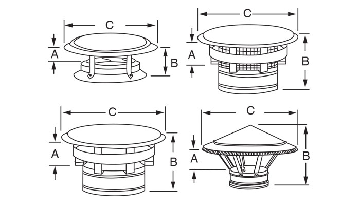
Regular Rain Cap
The regular rain cap is secured to the last length of the chimney by twist-lock assembly (CI-25) or centering coupler (CI-50) + locking band (not supplied). The CU2 rain cap comes with a spark arrester for Ø 305 to 457 mm (12 to 18 inches). (*) From Ø 508 and beyond, it comes complete with braces. -
Short Termination
The short termination cap is secured to the last length of the chimney by a centering coupler + locking band (not supplied) available for CI-50. When the chimney system is terminated with a short termination, an insulated drain tee cap must be installed. -
Finishing Cap
The finishing cap is secured to the last length of the chimney by twist-lock assembly. (Available for CI-25). When the chimney system is terminated with a finishing cap, an insulated drain tee cap must be installed. -
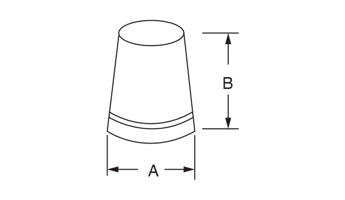
Finishing Cone
This finishing cone is secured to the last length of the chimney by twist-lock assembly (CI-25) or centering coupler (CI-50) + locking band (not supplied). The interior wall is flush with the inner lining of the chimney length, therefore producing a better draft: only the outer casing is cone-shaped. When the chimney system is terminated with a finishing cone, an insulated rain tee cap must be installed. -
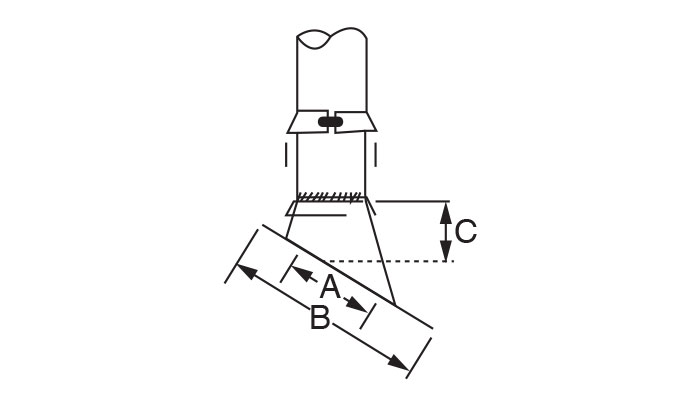
Adjustable Roof Flashing 30° to 45°
This component seals a chimney length extending from a roof with a 30° to 45° pitch. The roof plate is made of galvalume or aluminum while the flashing cone and the storm collar are made of galvalume steel. It comes complete with a storm collar. The storm collar must be sealed with silicone caulking. -
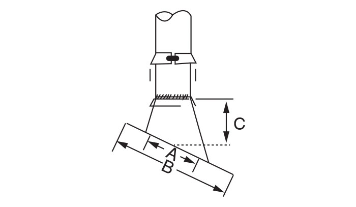
Adjustable Roof Flashing 5° to 30°
This component seals a chimney length extending from a roof with a 5° to 30° pitch. The roof plate is made of galvalume or aluminum while the flashing cone and the storm collar are made of galvalume steel. It comes complete with a storm collar. The storm collar must be sealed with silicone caulking. -
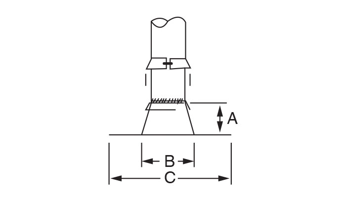
Flat Roof Flashing
This component seals a chimney length extending from a flat or very slightly sloped (no more than 5° pitch) roof. The roof plate, the flashing cone and the storm collar are made of galvalume steel. It comes complete with a storm collar. The storm collar must be sealed with silicone caulking. -
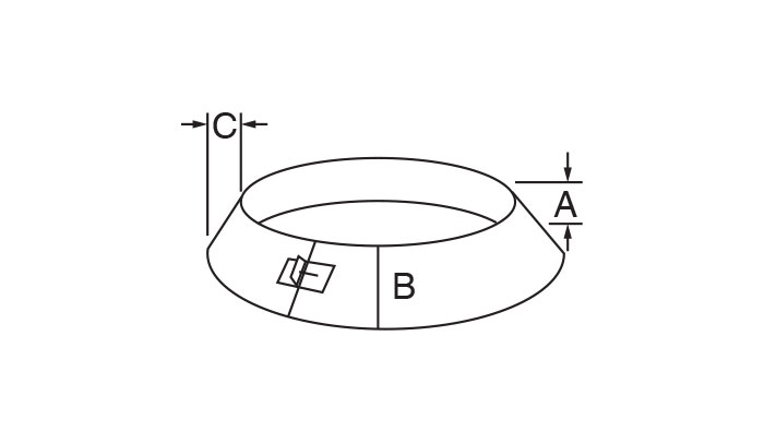
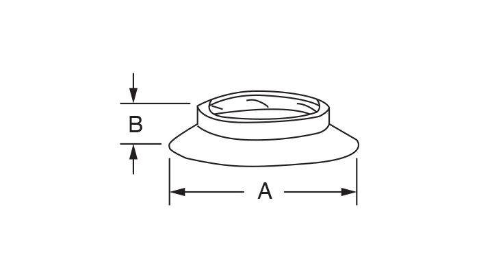
Storm Collar
Designed to fit over flashings of any kind, it ensures a watertight seal between the chimney’s external casing and the flashing. The storm collar must be sealed with silicone caulking. Provided with all roof flashings. -
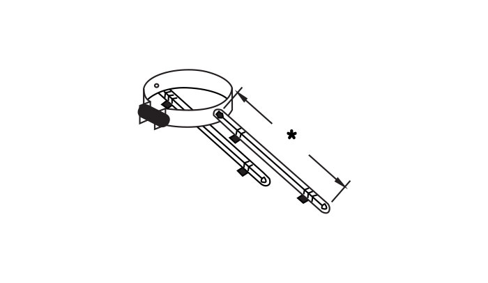
Roof Brace (BT)
This component comes complete with tightening collar and adjustable legs. Used to stabilize the CI chimney section extending beyond the roof in areas subjected to high winds or lengths extending 1.5 m to 3 m (5 to 10 ft.) from the last support or attachment point. *The legs are adjustable from 33 to 60 inches. Made of galvalume steel. -
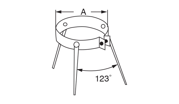
Guy Wire Band (BH)
Attached to the outer casing of the chimney, it is designed to hold 3 guy wires at a 120-degree angle to stabilize a CI chimney section extending from 1.5 m (5 ft.) to 4 m (13 ft.) beyond the last rooftop support (guy wires not included). Use three 5 mm (316 inch) guy wires, 120 degrees apart. Made of stainless steel. -
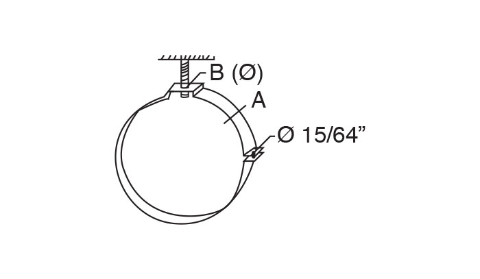
Suspension Band
Stabilizes and supports the CI chimney section used in a horizontal application. Makes it possible to suspend CI chimney sections using a threaded rod attach to the ceiling of the boiler room or any point. This support is needed every 2.00 m (6.6 ft) (for CI-25 flue or CI-50 flue). Made of stainless steel (BDSC). Also available in galvalume (BDSE). -
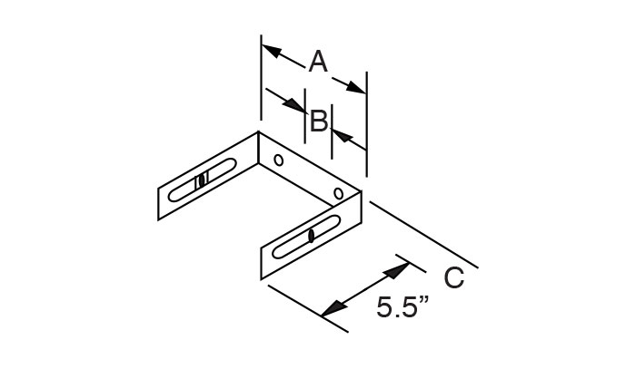
Wall Band Extension
Attached to the wall band, it is designed to extend the clearance between the chimney and wall surface by 50 mm to 85 mm (2 to 3.25 inches). A bolt and slot configuration allow the adjustment. Should always be used in UL-103HT application on masonry fireplace. Keeps the outer casing of the flue 100 mm to 135 mm (4 to 5.25 inches) from the wall surface. Made of stainless steel BEC (exterior use) or galvanized steel BEF (interior use). -
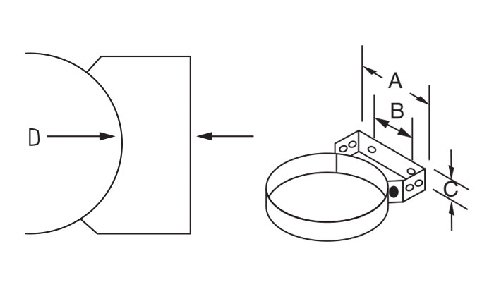
Wall Band
Designed for interior or exterior use, this band stabilizes the chimney along a vertical or diagonal surface: wall, mast, partition, joist... The band also ensures a minimum clearance of 50 mm (2 inches) between the outer casing of the chimney and the surface to which it is attached. A greater clearance requires the use of a wall band extension. Wall bands should be installed every 2.5 m (8 ft.) from any support in exterior installations, and 3 m (10 ft.) from supports in interior installations. Exterior use: band and attachment made of 304 stainless steel (BMC). Interior use: band made of galvalume steel and attachment made of galvanized steel (BMEF) -
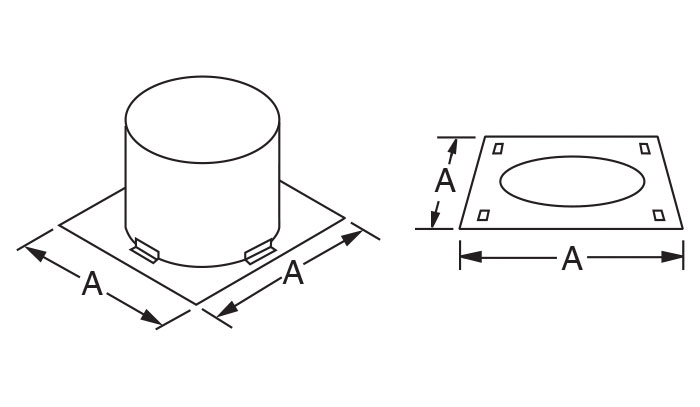
Firestop Radiation Shield
Attached on and/or under a floor or on both sides of a partition (CI-50), it serves to position the chimney whenever it passes through a floor, slab or joist, maintaining a minimum 50 mm (2-inch) clearance between the external casing of the flue and surrounding combustible materials. No section join must be in the ceiling/floor space. Made of galvalume steel. -
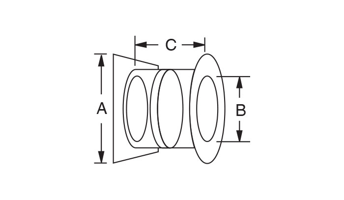
Wall Radiation Shield
Protects combustible materials when the chimney passes through a horizontal opening. A decorative plate painted in matte black provides an interior finish Supplied only in sizes of 152, 178, 203 and 254 mm (6, 7, 8 and 10 inches). The shield ensures a 50 mm (2-inch) safety clearance between the outer casing of the flue and surrounding materials. Adjustable to adapt to the thickness of the wall. Made of galvalume steel. *Not UL/ULC listed. -
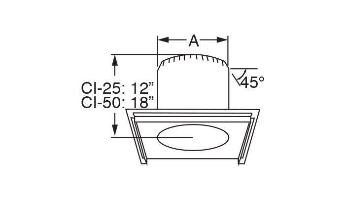
Radiation Shield
Protects combustible materials when the chimney passes through a floor, ceiling or an attic. The radiation shield ensures a 50 mm (2-inch) safety clearance between the outer casing of the flue and surrounding materials. No insulation should be inserted between the outer casing of the chimney and the interior surface of the radiation shield. Made of galvalume steel. *FPHT for UL-103 HT application on masonry fireplace only. Ensures a 100 mm (4-inch) clearance to combustibles. -
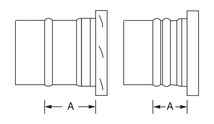
Adapter CT/CI
This adaptor is designed to connect the CT chimney to a CI chimney having an identical Ø. -
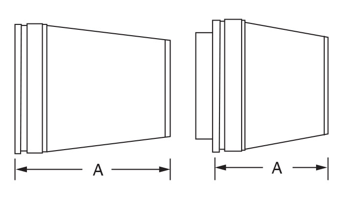
Adapter CI/CT
This adaptor is designed to connect the CI chimney to a CT chimney having an identical Ø. -
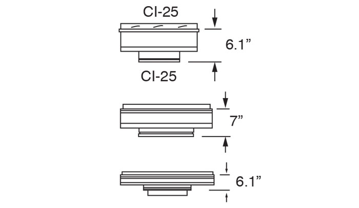
Step Increaser
This step increaser is needed for differences of more than two steps in size are required. Example: To order a step increaser 10 in. to 16 in.: CI10 SI 16. -
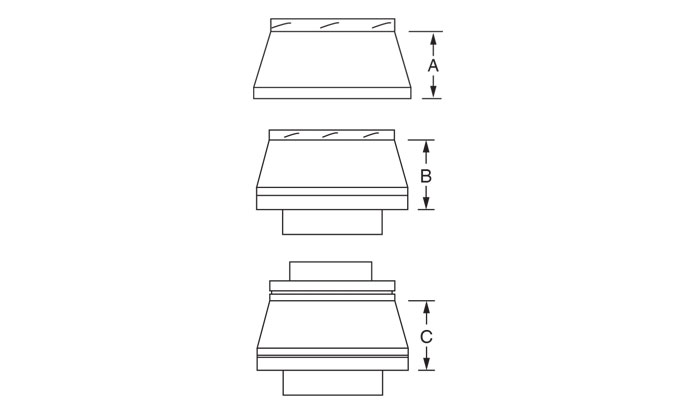
Reducer/Increaser
It is designed with a tapered shape to connect the CI chimney to an outlet one or two sizes greater or smaller. Example: To order a reducer 16 in. to 14 in.: CI16 RI 14; To order an increaser 16in. to 20 in.: CI16 RI20. -
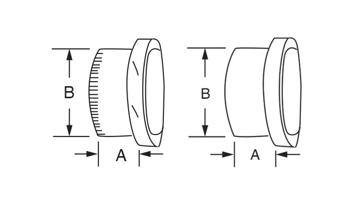
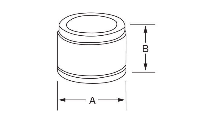
Flue Extension
This cylindrical component is designed to connect the CI chimney to an outlet having an identical Ø, or to a tapered adapting sleeve made by the installer. The crimped end is slightly tapered for ease of assembly. Note: the flue extension on the CI-50 is incorporated in every length. -
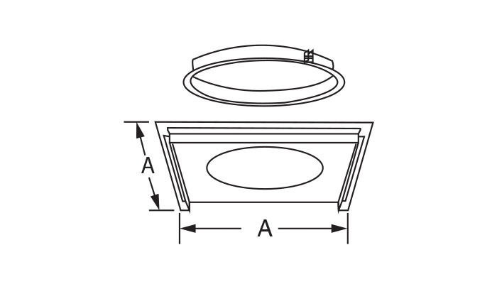
Floor Support
Supports the flue on a slab, floor or joist. Provides a minimum 50 mm (2-inch) clearance between the outer casing of the chimney and combustible materials around it. A tightening collar, locked around the flue and secured to the chimney be self-tapping screws (supplied), rests on a horizontal plate screwed or nailed to the floor. (See loadbearing chart on page 6) Made of galvanized steel. Can be used with a firestop spacer attached beneat the ceiling, making it possible to position the chimney and seal the space around the opening. *SDHT for UL-103HT application on masonry fireplace only. -
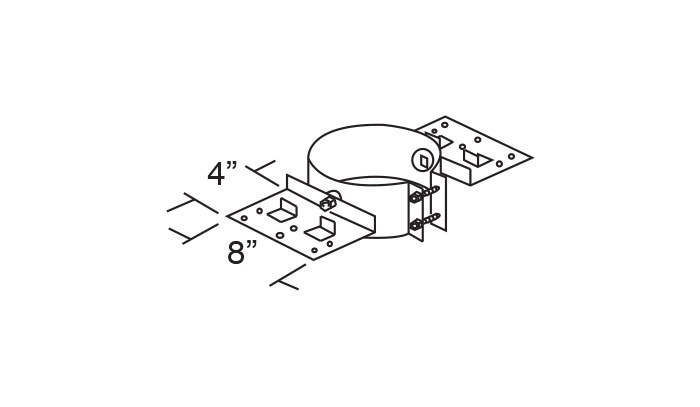
Roof Support (ST/STHT)
Complementary support usually attached to a roof structure. Two adjustable plates screwed to the structure adapt to the pitch of the roof. A tightening collar attached to these two plates locks around the flue and is secured by self-tapping screws (supplied). (See loadbearing chart on page 4) Made of galvalume steel. *SDHT for UL-103HT application on masonry fireplace only. -
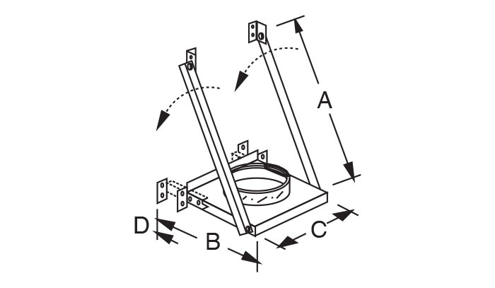
Wall Support
Supports the chimney at the base of the installation, or along a wall or other vertical surface serving as an intermediate support. This support is attached to the wall structure. It comes with a tightening collar locked around the chimney and secured by self-tapping screws (supplied). The collar rests on a horizontal plate. When used as a base support, it lends itself to the addition of an insulated tee cap or drain tee cap. Available in galvanized steel for CI-50 (SMIF) or galvalume for CI-25 (SMIE) or stainless steel in both series (SMIC). (See chart for loadbearing capacity on page 6). -
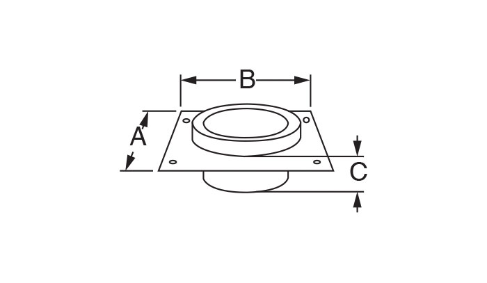
Anchor Plate
It is sealed to the lintel of a masonry chimney or provides a positive connection between the chimney and a boiler. It receives and supports the first section of the assembled chimney. (See loadbearing chart on page 6). Made of galvanized steel. -
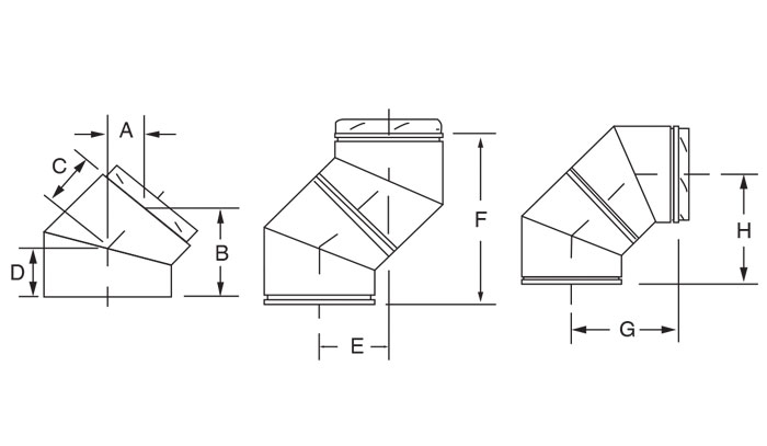
45° Insulated Elbow
Allows the 45° offset of a horizontal or vertical section. It can be used in combination with other elbows to form offsets at specific angles (no attachment notches in the female coupler) or to deviate the chimney. It comes complete with a locking band. -
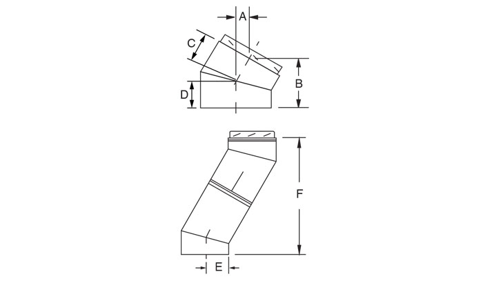
30° Insulated Elbow
Allows the 30° offset of a horizontal or vertical section. It can be used in combination with other elbows to form offsets at specific angles (no attachment notches in the female coupler) or to deviate the chimney. It comes with a locking band. -
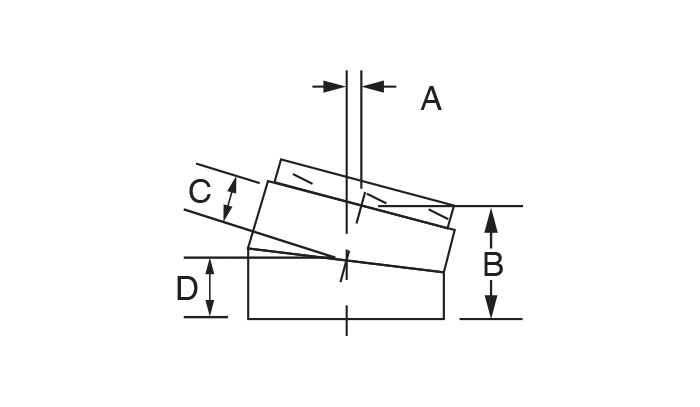
15° Insulated Elbow
Allows the 15° offset of a horizontal or vertical section. It can be used in combination with other elbows to form offsets at specific angles (no attachment notches in the female coupler) or to deviate the chimney. It comes complete with a locking band. -
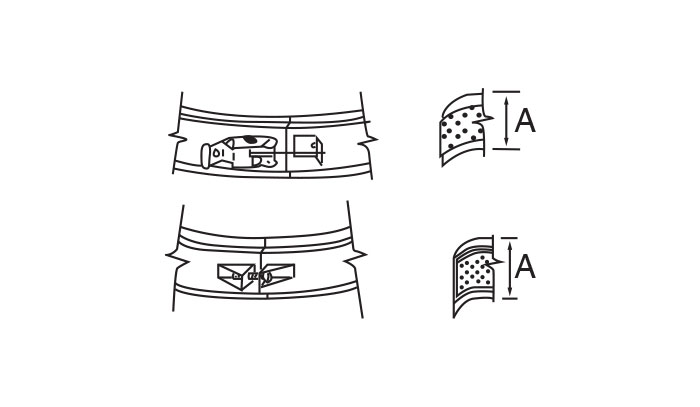
Locking Band
It is imperative that a locking band be fitted over each assembly joint to ensure the tightness of the joint and the sturdiness of the assembly.Featuring a ceramic flat gasket, the band positions itself around the section at the joint. Made of stainless steel, it automatically comes with all chimney components except the roof terminations. -
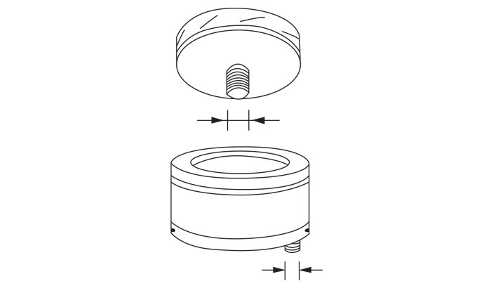
Insulated Drain Tee Cap
This component is fitted at the base of a tee installed vertically. It makes it possible to collect and drain rain water and condensates Removable, it provides easy access for chimney maintenance or inspection. Threaded nipple (Ø 1 in. - 11½ NPT) -
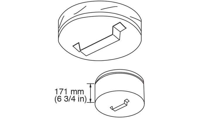
Insulated Tee Cap
Designed to seal the base or lateral opening of a tee, it also prevents cooling of the gases. It is removable, providing easy access for chimney maintenance or inspection. -
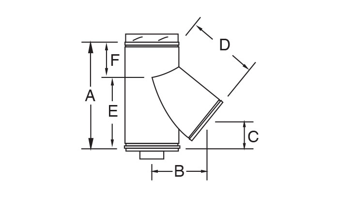
135° Tee
It performs the same function as the 90° tee, but is designed for diagonal connections that reduce heat loss and facilitate the upward flow of gases. It is generally used in conjunction with a 45° elbow to permit the connection of a horizontal flue 9for listing of assembly sizes, see chart on page 9). The 135° tee comes complete with an inspecting tee cap (TV). (Loadbearing capacity: see chart on page 4) -
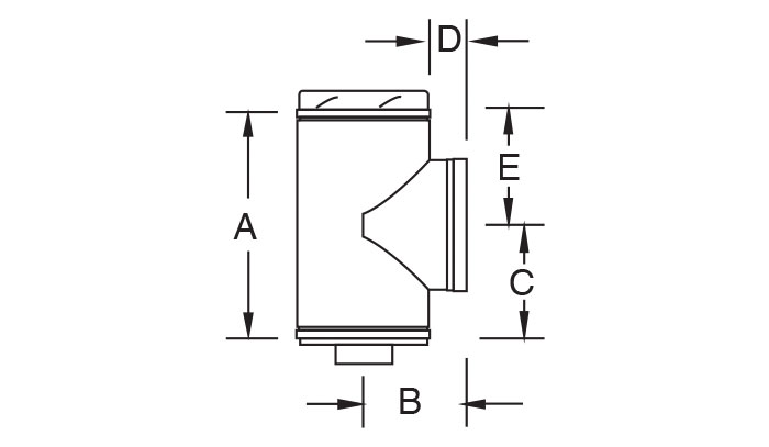
90° Tee
Most often located at the base of a chimney, it makes it possible to connect the flue to the heating appliance. It can be installed at any horizontal or vertical point along the chimney to connect a length or ensure access for inspetion or cleaning. May be used in breeching a chimney to allow installation of a draft damper. The 90° tee comes complete with an inspecting tee cap (TV). (Loadbearing capacity: see chart on page 4). -
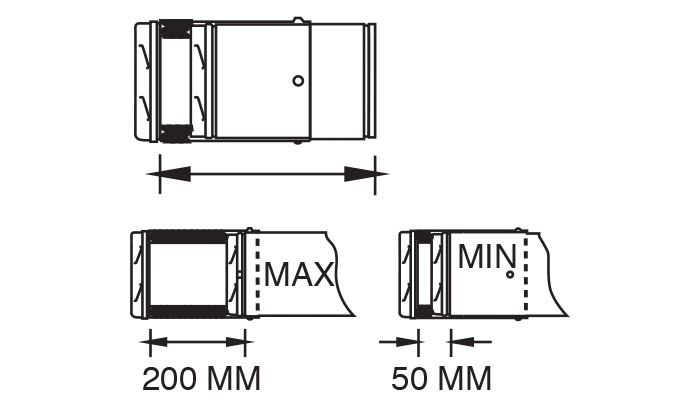
Adjustable Insulated Lengths
Used in combination with straight insulated lengths, the adjustable length makes it possible to fit a CI length perfectly, in horizontal and diagonal installations. It also makes it possible to disassembly couplers easily. This length comes with a locking band that must properly cover each assembly join. IMPORTANT: The adjustable insulated length is not designed as a loadbearing component. Its vertical installation requires an appropriate support on the section above it to bear the weight of the remaining installations. -
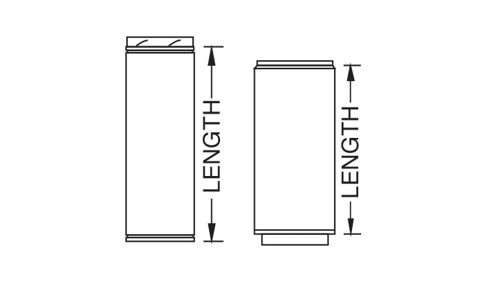
Straight Lengths
Available in 12 diameters and 4 standard effective lengths of 4”, 10”, 20”, and 39 3/8” for CI-25 as well as 3 standard lengths of 11 3/8”, 17 3/8” and 35 3/8” for CI-50. ALL LENGTHS ARE EFFECTIVE METRIC SIZES AFTER ASSEMBLY. These components can be combined to meet the needs of any horizontal, diagonal or vertical installation. They come complete with a locking band which must properly cover each assembly joint.


